IMOLD for SolidWorks is a SolidWorks environment the most powerful mold design products, mold designers can quickly design, and ready for preview. Using its automated tools or interactive tools, such as automatic generation tool offline, internal / hole surface and edge segmentation tools nuclear development tools, IMOLD provide functionality not work with other mold design system in the same breath.
Module:
Data preparation, target control, core and hole generation, layout, feeding system design, Moldbase design, ejection design, inserts design, elevator design, cooling system design, component library, intelligent screw, BOM generator, IMOLD sketches, 15 kinds IMOLD tools.
SolidWorks software can open different types of CAD files, whether you receive is an intermediate file format, SolidWorks software allows you to get one of the geometry. Because data errors can occur when other design systems from import geometry, SolidWorks software provides a complete set of tools to fix imported files and clean up geometry. SolidWorks software also provides diagnostic tools to help you entities joined together. Use MoldflowXpress, you can estimate whether you can create an acceptable mold based on the original 3D solid mold plastic injection parts. You can even assess moldability based on geometry, injection location, type of material and processing conditions. This information allows you to easily determine the number of gateways, as well as the required number of runners and cooling systems. You can use the SolidWorks undercut detection capabilities to identify needs some action in order to remove the parts that came with the part from the mold area. SolidWorks software also includes a "thickness inspection", you can detect the thickness of the part can not reach the specified area. If you do not correct thickness would not be enough, then problems may arise during manufacture.
You can apply a shrinkage factor to the part based materials. And automatic recommendations based on parts of the draft direction best parting line, an area and identify all the parts of the draft is not sufficient; you can also adjust the draft surface with respect to any adjacent edges angle. The software also offers a range of solid modeling and surfacing tools, even the most complex molds can easily create parting surfaces. Once you have created parting surfaces, you can use the "cutting Split" command will mold into two entities. You can then use these entities to create a multi-body part with the original design of the assembly is associated. SolidWorks Design library provides a platform for developing company standards, which includes features, parts and assembly models, you can drag and drop these models to design new models.
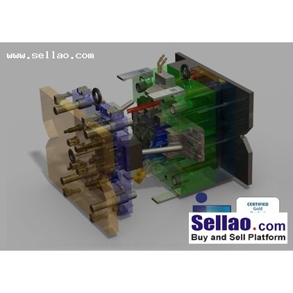
SolidWorks provides tools that allow you to very easily generate all the core and cavity machining required geometry of the part design.
SolidWorks software makes it easy to generate production-level 2D drawings from 3D assembly model. You only need to draw a line in SolidWorks, you can draw a cross-sectional view of the assembly, and automatic generation of the drawing. You can always add or change the size, size instantly updated to conform to the design change. You can quickly create exploded views of how to describe the operation of the mold: first arranging components in 3D, and then select the cross section to define 2D detailed drawing views. In addition, the type balloons in the bill of materials can easily annotate these views. |


 Print View
  Watch this Item
  Send this Auction to a Friend